MPLS Layer 3 VPNs
This post is the continuation of the previous post I made on Basic MPLS. In this post, I will talk about the different steps in order to configure MPLS Layer 3 VPNs which include the PE-CE routing protocols configuration with RIP, EIGRP and OSPF. I will also talk about the different loop prevention rules used when using OSPF as a PE-CE routing protocol. Finally I will conclude this post by talking about OSPF Sham-link.
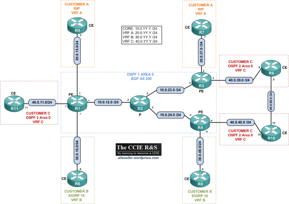
In this topic, I will use the following topology:
Platform/IOS: Cisco 2691/12.4(15)T11 Adv IP services
VRFs:
- Customer A: VRF A | IGP: RIP
- Customer B: VRF B | IGP: EIGRP
- Customer C: VRF C | IGP: OSPF 2 Area 0
- ISP: Core IGP: OSPF 1 Area 0 | MP-BGP AS 200
Addressing: See topology. All the routers are configured with a Loopback IP and the format X.X.X.X /32 where X is the router number.
Just as a reminder, VRF Lite can be used to extend VRFs beyond a single router by properly mapping the VRFs to the links connecting two routers. This results in “parallel” VPNs being run across multiple devices which is the most basic way to build VPNs. However this solution has poor scalability, as you need to allocate a dedicated inter-router link for every VPN.
A better alternative is using MPLS VPNs. In this post I will only talk about MPLS Layer 3 VPNs. MPLS VPNs is a combination of different protocols and technologies. MPLS VPNs uses MPLS technology as the fundament and build MP-BGP sessions above MPLS in order to exchange VPN routes. BGP functionality has been enhanced to handle the “VRF” specific routes. A new special MP-BGP (multiprotocol BGP) address family named “VPNv4” (VPN IPv4) has been added to BGP along with new NLRI format.
Let´s start with the configuration of MPLS in the core ISP.
MPLS configuration of the Core ISP
Let´s start by configuring the MPLS core of the ISP. To do we will use LDP (see my previous post on Basic MPLS to see how to configure MPLS in detail). Note that OSPF has already been configured in the core ISP and that all loopbacks are configured as /32. All the loopback have the format IP address: X.X.X.X/32 where X is the router number.
Here is the configuration template we will use to enable LDP on all the ISP core routers:
As we are running OSPF we can use the mpls ldp autoconfig feature so we don´t need to enable LDP on all the interfaces. As soon as LDP is enabled, LDP sends discovery UDP packets to the multicast IP 224.0.0.2:646 with the LDP router-ID corresponding to each router sending these packets. The router-ID will be used to build the LDP session between the LDP enabled routers once they have discovered each other. After the TCP session is established the LDP neighbors will exchange prefix and label bindings resulting in the LFIB population:
So R1 has learned these label/prefix bindings from R2. So for example for the loopback IP of R4 which is 4.4.4.4/32 if R1 receive a packet for this destination IP it will insert a MPLS label with a value of 18 between the L2 Frame header and the Layer IP header. This inserted label is also called the shim header. R1 will also change the L2 protocol identifier (PID) value in the L2 frame header to indicate that the next protocol is MPLS and not IP. As I explained in this post (Basic MPLS) the pop tag simply means that R1 should remove any label when forwarding a packet to the next hop MPLS router.
In our case we will only need labels for the loopback IP addresses which will be used to build the MB-BGP sessions between the PEs routers. So in order to force the routers to generate labels for the loopbacks only we configure the following commands on all the LDP routers:
Let´s check the LFIB of R1 again:
So now R1 has only LDP information for the loopbacks IP addresses.
Establishing MP-BGP sessions between the PEs
Let´s now establish the MP-iBGP sessions between the PEs in order later to be able to exchange the VPN routes between the different CE sites. For the configuration of the MP-iBGP sessions we use the following template on all the PE routers:
We establish a Full mesh MP-iBGP session between the 3 PEs and disable the IPv4 unicast address-family as in this example we will only exchange VPNv4 prefixes and therefore we only use the VPNv4 address-family.
Side note: We use the loopback IP addresses in order to peer with each BGP neighbors in order to avoid traffic black hole (decribed in my post on Basic MPLS). Otherwise the MPLS transport label will be removed one hop to soon and one of the P routers will be faced with the VPN label (I will explain it later) and drop the traffic as it will not be able to interpret this label.
So now we have the MP-iBGP sessions established between all the PEs and we can verify that on R1:
Perfect, that means we are almost ready to exchange VPN routes between the PE routers from the different CE customers. We need now to configure the respective VRFs on the different PEs as well as the different PE-CE routing protocols.
Configuring VPN VRFs
Please refer to the topology diagram at the beginning of the post to see the different name of the VRFs.
By default all the interfaces (physical or sub-interfaces) on a router are assigned to a VRF known as the global VRF. In order to create a new VRF, issue the command ip vrf <VRF_NAME> which opens up the VRF configuration context mode. After this we need to configure a Route Distinguisher (RD) for each VRF using the command rd X:Y where X and Y are 32 bits numbers. The RD is a 64 bit prefix prepended to every route in the respective VRF routing table. This prefix is needed in order to make all the prefixes from the different customers unique. Imagine for example that Customer A advertise a prefix of 10.10.10.0/24 and Customer B also. Well, on the PEs this will not be a problem as each of these prefix will be in different VRFs (VRFA for Customer A and VRFB for Customer B) but the issue arise for example when using BGP Route Reflectors as theses routers will see all the customers routes from all the VRFs but the RR are not configured with VRFs which will cause problems when reflecting the different prefixes. So thanks to the RD all the prefix from each VRF are unique. An IPV4 prefix prepended with a RD prefix is called a VPNv4 prefix and it is 96 bits long (32+64).
The common format for a RD is using the combination ASN:NN where ASN is the autonomous system number and NN is the VRF number inside the router or more globally, the VPN number within the ASN. Alternatively, you may use the format IP-Address:NN where IP is the router’s IP address and NN is the VRF name. The second format properly reflects the feature of RD being a local distinguisher, but using the format ASN:NN is more popular and common, as it easily associates a VRF with a particular VPN in the network.
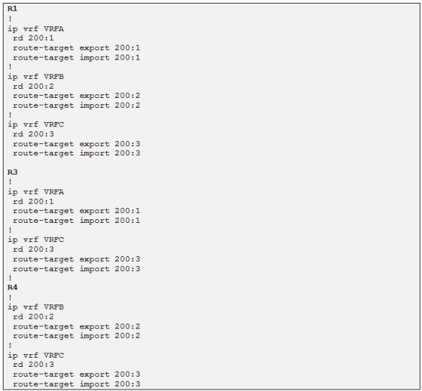
In our example we will use the following format for the different VRFs RD:
- VRF A: rd=200:1
- VRF B: rd=200:2
- VRF C: rd=200:3
As the RD is locally significant it cannot be used as a VPN route membership. This is because the same RD may eventually belong to multiple VRFs. So when a BGP PE router is receiving a VPNv4 route from another PE it has to know in which VRF to import it. So a new BGP extended community has been defined for MP-BGP to work properly with VPNv4 prefix exchange and it is called a Route Target (RT).
A RT is a BGP extended communities attribute which is encoded as a 64 bit value and defines the VPN membership of a VPNv4 prefix. When VPNv4 prefixes are exchanged between PEs, the defined RT is attached to every route exported from the VRF to MP-BGP. On the other end when a PE router receives a VPNv4 prefix it looks at the attached RT and check if it has any VRF matching the RT attached to the route. If the PE has the attached RT configured as an import RT the VPNv4 prefix will be imported into the corresponding VRF otherwise the prefix will be dropped.
RT are defined by specifying under the VRF configuration, the command route-target export X:Y. You may specify as many export commands as you want to tag prefixes with multiple attributes. On the receiving side, the VRF will import the BGP VPNv4 prefixes with the route-targets matching the local command route target import X:Y. The import process is based entirely on the route targets, and not on the RDs. If the imported routes used to have RDs different from the one used by the local VRF, they are “naturalized” by having the RD changed to the local value.
In our example we will use the following format for the different VRFs RT:
- VRF A: rt=200:1 for both import and export
- VRF B: rt=200:2 for both import and export
- VRF C: rt=200:3 for both import and export
Now that we have the VRF format define for each Customer site let´s go ahead and configure the different VRFs on each PE:
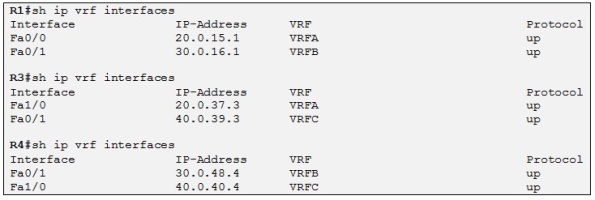
Now we just need to associate each VRF with the corresponding CE interface by using the ip vrf forwarding <VRF NAME> command under the corresponding interface.
Perfect! Each CE router is placed in the correct VRF. The next step will be to configure PE-CE routing protocols at each site so the ISP and the different customers can exchange prefixes.
Configuring PE-CE routing protocols
In our topology we are using RIP, EIGRP and OSPF as the PE-CE routing protocols. Note that each CE router is already configured with the routing protocol shown on the topology diagram at the beginning of this post. All the CE routers are advertising their loopbacks in the respective routing protocols.
The per-VRF routing protocols can be configured in these two ways on the PE routers:
- Per-VRF routing protocols can be configured as individual address families (routing protocol context) belonging to the same routing process (similar to BGP).
- Per-VRF routing protocols can be configured as separate routing processes. This option is used for more complex routing protocols that need to maintain a separate topology database for each VRF (for example OSPF).
- RIP
Let´s start by configuring RIP VRF aware process:
Side note: The global RIP parameters entered in the scope of RIP router configuration are inherited by each routing context and can be overwritten if needed in each routing context.
We can now verify if R1has learned the loopback IP address of R5 through the RIP update:
So yes it has. Let´s enable RIP routing context on R3 also and then we can check if R3 is learning the loopback IP address of R7:
- EIGRP
Perfect! Let´s configure the routing context for EIGRP now:
Let´s now check if R1 learns the loopback IP of R6 through EIGRP:
Let´s enable EIGRP routing context on R4 also and then we can check if R4 is learning the loopback IP address of R8:
Perfect!
- OSPF
For now the Site of router C where R11 is connect is not enabled
Let´s now configure OSPF VRF aware process. To configure OSPF as a PE-CE routing protocol you need to start a separate OSPF process for each VRF in which you want to run OSPF. As the core ISP is using OSPF process 1 we will use process 2 for the PE-CE configuration.
Side Note: Note that the router-id must manually be configured as there is no loopback interface in VRFC.
Let´s check if R3 is learning the loopback IP of R9:
Perfect! Let´s configure OSPF VRF aware process on R4 and check if R4 learned the loopback IP of R10:
Alright, all the PE-CE routing protocols have been configured for the different sites. Now we need to configure VPNv4 prefix exchange between the PEs in order to exchange the customer routes between the different sites.
Configuring MP-BGP VPNv4 prefixes exchange
In order for the VPNv4 prefixes to be exchanged between PEs, the CE learned routes must be redistributed into BGP. When we created the different VRFs before the BGP process has automatically created an address family VRF for each VRF configured on the router. So now we just need to redistribute each CE routing protocol in the BGP routing context for the specific VRF as well as redistributing BGP into each CE routing protocol for the specific VRF
- Mutual Redistribution between RIP and BGP for VRFA
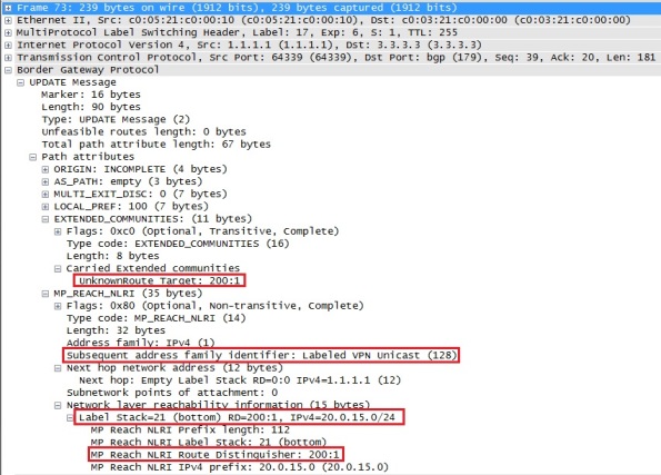
As soon as we redistribute RIP into the BGP process R1 advertise the Customer A prefixes to all its MB-iBGP neighbors. We can see how the BGP packet format looks like by using Wireshark to capture the MP-BGP VPNv4 updates sent by R1 to R3 and R4 for the prefix 20.0.15/24:
In the capture above we can see the RD prepended to the prefix and also that the configured RT is attached to the prefix. There is also a label attach to the route which I will talk about later on. Also note that this update is sent through the core using MPLS as we can see in the capture that the BGP update gets encapsulated with an MPLS label of 17 which corresponds to the loopback of R3. That means that the core P router (in this case R2) will only do label switching and not IPv4 routing.
Let´s check if R3 and R4 receive the VPNv4 prefixes advertise by R1:
So R3 is receiving both prefixes and we can clearly see the RD prepended to both prefixes (RD=200:1). Also the RT we configured earlier is attached to both prefixes. Let´s check if theses prefixes are in the BGP table of R3:
Yes they are! Let´s now check if R4 is receiving these prefixes:
So R4 is receiving both updates but it is not accepting neither of them and this is because we don´t have configured any import RT for VRF A (RT=200:1) on R4 only for VRF B and VRF C which is alright as R4 doesn´t have any customer in VRF A.
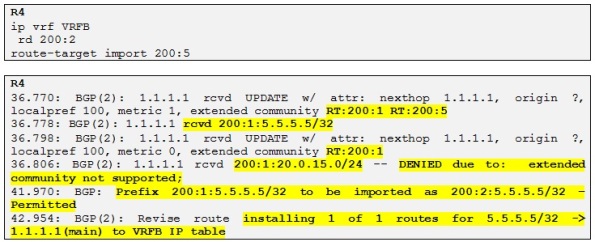
However if we wanted R4 to accept also the loopback of R5 in VRF B we could configure R1 to add an extra RT to this prefix when it is redistributing Customer A routes into the BGP process. Let´s try the following:
In the above configuration on R1 we simply add an extra RT to the current (RT=200:1) as we export the prefix 5.5.5.5/32 into MP-BGP by using a Cisco IOS feature known as export/import maps.
We can see in the above show output that R1 BGP process has added the extra RT 200:5 to the prefix 5.5.5.5/32.
So now let´s configure this new RT as import on R4 for VRF B:
So now R4 is accepting the prefix 5.5.5.5/32 advertised from R1 with two RTs attached and installing it in the routing table of VRFB .
Side note: In the output above we can also confirm that R4 is “naturalizing” the original RD of the prefix (200:1) to the RD configured in the VRFB.
Side note 2: In order for a prefix to be imported into a VRF there should be two conditions validated: 1) At least one of the RTs attached to the route matches one of the import RTs configured in a VRF. 2) The route is permitted by the import map. We didn´t use any import map in our example but we could have done that on R4 to filter which prefix we wanted to import into VRFB. Please also note that the export route-map performs only the attachment of the RT and cannot perform any filtering function.
So now, let´s have a look at the prefix 5.5.5.5/32 on R4:
We can clearly see in the output above that the prefix has been imported into VRFB and the RD value was 200:1 before. Also the prefix has both extended RT communities attached to it.
Perfect! Let´s redistribute RIP into BGP on R3 also and let´s verify that R1 receives these routes and install them in the routing table of VRFA:
Alright so R1 is receiving and installing both VPNv4 prefixes coming from R3.
Now we need to redistribute BGP into each CE routing protocol in order for the Customer A to get the routes exchanged for both sites. Let´s configure the following on both R1 and R3:
Side note: We use the keyword “metric transparent” which means that the RIP metric will be recovered from the BGP MED attribute which in turn is copied from RIP metric learned at the remote site. This allows for transparent preservation of RIPv2 metric values across the VPN and better patch selection in case of backdoor links. Also the metric preservation causes the whole MPLS VPN backbone to appear as a single hop to the CE routers
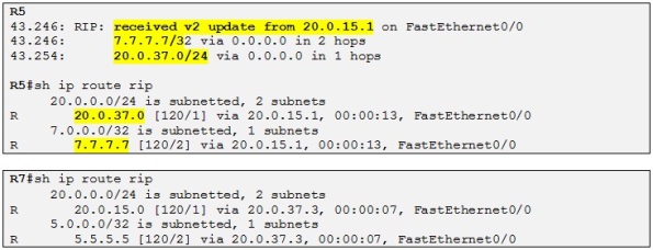
Let´s check if R5 and R7 receive their respective routes:
And yes they do! Note that as explained above the MPLS VPN backbone appears as a single hop. R7 advertise a metric of 1 for 7.7.7.7/32 and R5 receives 7.7.7.7/32 with a metric of 2. Also note that RIP adds a metric of 1 when sending an update and not when receiving it.
It looks like that customer A sites have reachability to each other across the MPLS VPN backbone of the ISP. So let´s test it! We will focus on R5 trying to ping the loopback of R7 (7.7.7.7 /32):
So yes, we can confirm that there is reachability between Customer A sites. I would like to explain what the label 22 that we can see in the traceroute output is. First recall from my previous post on MPLS (Basic MPLS) that the first label 17 is the transport label, which is the label used to reach the BGP next-hop which is in this case R3 loopback BGP peering IP:
When R1 do a routing lookup for the IP destination 7.7.7.7 he knows that the next hop is 3.3.3.3 which is associated with the label 17 in LFIB, previously advertised to R1 by R2:
So R1 already knows the interface where to route the packet. Then the CEF process will associate the next-hop 10.0.12.2 with the label 17 therefore when R1 is sending traffic to 3.3.3.3 it will always use the label 17. This label is known as the transport label which is the one used to reach the neighbor PE. The thing is that when R1 needs to reach the loopback of R7 it needs somehow to encode this information in an MPLS label stack because otherwise R3 will not know in which VRF to make the routing lookup for the destination prefix 7.7.7.7 /32. So another label is used apart from the transport label which is called the VPN label. The VPN label is the inner label in the MPLS label stack which is situated just above the transport label which is also known at the outer label. The VPN label is created and distributed by the MP-BGP process when exchanging the different VPNv4 prefix between the PE routers. In our case R3 has allocated a VPN label of 22 (see the sh bgp output above) to the prefix 7.7.7.7 /32 and has attached this VPN label to the VPNv4 update for this prefix when advertising it to its VPNv4 neighbors.
So When R2 pop up the transport label 17, R3 receives a MPLS labeled packet with a label of 22 and knows that it has to do a routing lookup in the VRFA for 7.7.7.7 /32:
Now let´s do mutual redistribution for Customer B sites that are running EIGRP with the ISP.
- Mutual Redistribution between EIGRP and BGP for VRFB
One issue with transporting EIGRP routes over MP-BGP is preserving the original metric values, the route type, the source AS# and the remote Router ID. These are encoded using special BGP extended community attributes to allow the remote site to properly decode the incoming routing update information. Six extended BGP communities have been defined to carry the EIGRP routes across the MPLS backbone via MP-iBGP. The table below shows the different BGP extended communities for EIGRP PE-CE routing:
Source: MPLS configuration on Cisco IOS software, Author: Lancy Lobo
Alright, let´s perform mutual redistribution for Customer B on R1 and R4:
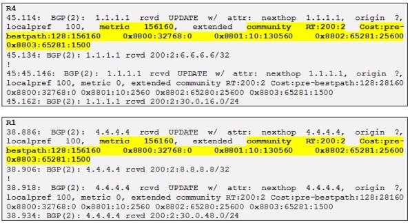
First we redistribute EIGRP into BGP on R1 and R4. We can then check if R1 and R4 are receiving these prefixes:
So both R1 and R4 are receiving the VPNv4 prefixes from each other and we can see the different extended communities attached to the prefixes. By referring to the table above let´s decode the following BGP extended communities values for the prefix 4.4.4.4/32 received on R1 from R4:
- 0x8800 indicates that the route is internal as flags=32768. If flag 0 it would have been external
- 0x8801 indicates the AS and delay where 10 is the AS and 130560 is the delay which is: (130560*10)/256=5100 microseconds
- 0x8802 indicates reliability which is 100% that is 65281=0xFF01 where FF indicates reliability of 255/255 and 01 indicates that the prefix is one hop away
- 0x880e indicates the load and the MTU. So 65281 is 0xFF01 where FF is reserved and 01 indicates the load =1/255 and 1500 indicates the MTU.
There is a last extended community attribute in the debug output which is the BGP cost community which is used to change the BGP selection process that by default prefer locally originated prefix (as the weight is 32768) over received BGP prefixes. So in order to resolve the issue where the remote site has better EIGRP metric to reach the destination, EIGRP prefixes redistributed into MP-BGP will have the cost attribute set to their composite metric so the BGP process will honor the cost attribute before any other best-path selection option if the attribute is present.
In our example for 4.4.4.4/32 received on R1 the cost is equal to 128:156160 where 128 indicates that is an internal route and 156160 is the composite metric calculated by R1 to reach 4.4.4.4/32
There is another attribute which is called EIGRP SoO Attribute which is used to prevent routing loops in multihomed environments where two-way redistribution is used. I will not talk about it in this post as the topology used is not using multihomed for Customer B. It will be interesting to talk about in another post though.
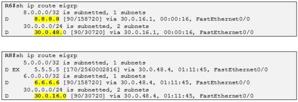
Ok, let´s go ahead and redistribute BGP into EIGRP at both Customer B sites and check if R6 and R8 get the prefixes:
Perfect! So Customer B sites have reachability to each other through the MPLS VPN backbone. The external EIGRP route seen on R8 is the RIP route from R5 that we imported in VRFB on R4 before with the import map.
Side note: Notice that the routes received at each site are not seen as EIGRP external and that is thanks to BGP extended communities attached to the VPNv4 prefixes we saw before. So when BGP is redistributed into EIGRP all the original EIGRP attributes are preserved such as AS, composite metric, etc. If you had redistribute a route into EIGRP at R6 for example, R8 will see this route as EXT and R1 (Redistributing PE) will have had the extended community 0x8804 to it encoding the R-ID of R6 as the router-ID is used for loop prevention when using redistribution with EIGRP.
Let´s now perform mutual redistribution for Customer C.
- Mutual Redistribution between OSPF and BGP for VRFC
Prior to read this section I invite you to read this post (Basic OSPF v2 in depth) if you are not familiar with OSPF and the different types of LSAs.
OSPF as PE-CE routing protocol in MPLS VPN environment is define in RFC 4577
Note that R9 and R10 have a backdoor link between their sites which is shutdown for now.
When using OSPF as the PE-CE routing protocol in combination with MP-BGP, the ISP MPLS VPN backbone is considered by OSPF as a “super area 0” that is used to link all OSPF area at different sites. This special “virtual area” is called the OSPF super-backbone and is emulated by passing OSPF VRF routing information in MP-BGP updates. The result of using the OSPF super backbone is that you don´t need to use area 0 at all as the super backbone performs the same function thus we can have non-zero OSPF areas at different sites connecting via the MP-BGP mesh without the need for area 0 at any site.
All OSPF routes redistributed into MP-BGP are treated as inter-area routes as they enter the super-backbone from other areas even if they belong to the same area number at different sites and this because the LSAs cross the super-backbone. All the PEs are seen as Area Border Router (ABR) from the CE router perspective. MP-BGP uses three extended communities in order to transparently transport OSPF prefix over the MPLS VPN backbone. Let´s see what the different extended communities are:
- The first one is known as the OSPF domain-id. This attribute is equal to OSPF process number on the local router (PE). It is assumed that you configured all OSPF process number for the same VPN using the same process number. If the domain-id is different, OSPF will interpret all such prefixes as if they are Type-5 External LSAs.
- The second one is known as the OSPF Route Type which has 3 significant fields: source area, route-type and option and has the following format: X:Y:Z.. X represents the area number and Y represents the LSA type (LSA 3, 5,7). Z is the option field and defines the metric type for LSA Type-5 or Type-7 (E1, E2, N1, N2). This attribute helps the BGP process to track the originating OSPF LSA type in order to make the correct redistribution from MP-BGP into OSPF. So if the origination LSA is type 5, MP-BGP will encode that and when doing redistribution on the other end of the MPLS VPN backbone, the PE will know that it should redistribute this route has LSA Type-5 into OSPF.
- The third one is the OSPF router ID. Identifies the router ID of the PE in the relevant VRF instance of OSPF.
The BGP MED attribute is used to carry the OSPF metric.
Then OSPF defines different loop prevention mechanism when used with MP-BGP:
- All LSA Type-3 generated from the routes redistributed from MP-BGP into OSPF have a special “down bit” set in the LSA headers. If a router receives a summary-LSA with the down bit set on an interface that belongs to a VRF it simply drops the LSA. That will be the case when a PE router redistributes into OSPF and CE advertise the route through a backdoor link to another CE which in turn advertise the route to the other PE, then this PE router will prefer the route through OSPF as the OSPF AD (110) is better than iBGP (200) and the route will be advertised back to the origination PE which will create a routing loop. So the down bit dictates that the PE router should never redistribute a route from OSPF to MP-BGP if the down bit is set. This is a similar behavior to manual tagging. However if a CE is running VRF-lite that could be an undesirable behavior as the route will not be passed through the backdoor link so this default loop-prevention capability can be disabled with the command: capability vrf-lite on the CE router.
There is another OSPF feature used when using MP-BGP related with the down bit and this has to do with optimal routing in order to avoid that the Customer OSPF domain is used as a transit parts of the MPLS VPN network. For example as I described before the receiving PE receive the same prefix via MP-BGP and OSPF if the Customer has a backdoor link between its sites. As the down bit is set the receiving PE will not redistribute routes with the down bit set from OSFP to MP-BGP and that is the desired behavior to avoid routing loop. However the receiving PE will prefer to route for this prefix via the Customer OSFP domain than to route via the MPLS backbone and this because the AD of OSPF 110 is better than the AD of iBGP which is 200. This behavior will convert the Customer OSPF domain as a transit part of the MPLS network. To avoid that, for OSPF routes with the down bit set, the routing bit is cleared and these routes will therefore never enter the IP routing table even if they are selected as the best routes by the SPF algorithm. This result in the data packets always flowing through the MPLS VPN backbone following only the MP-BGP routes.
- The other loop prevention mechanism is similar to the previous one with LSA Type-3 but for LSA Type—5 this time. The down bit stops routing loops between MP-BGP and OSPF but cannot however stop the routing loops when redistributing between multiple OSPF domains. That is to say if a BGP PE router redistribute a non-OSPF route into an OSPF domain the down bit will be set and the route will be send to the CE router in OSPF domain 1. However when the CE router redistributes this route from OSPF domain 1 to 2, the down bit will be cleared and the receiving PE in OSPF domain 2 will create a loop by redistributing the route back into MB-BGP. Moreover the down bit is not supported in LSA Tpe-5. To avoid this scenario PE routers set the tag field equal to the BGP AS number when redistributing non-OSPF routes from MP-BGP to OSPF. The tag field is propagated between OSPF domain 1 and OSPF domain 2 and the receiving PE routers in OSPF domain 2 will filter external OSPF routes to MP-BGP with OSPF tag field AS number matching its BGP AS number effectively preventing routing loops. Note that only the PE router is inserting the tag field so if the redistribution happen in OSPF domain 1 by the CE router, manual tagging should be used in order to recreate the above automatic tagging process of MP-BGP.
Alright, that is it for the theory, let´s go ahead and have some fun and configure mutual BGP-OSPF redistribution on R3 and R4 for VRFC:
Fist let´s start by redistributing OSPF into MP-BGP on R3 and R4:
We can now check if R3 and R4 are receiving the different prefixes:
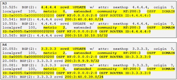
And yes they do! Let´s look at the different attributes which we explained before. Let´s take some reference prefix, for example the loopback of R10 which is 10.10.10.10/32 received by R3 from R4.
- OSPF domain ID: 0x0005:0x000000020200. The 0x02 is equal to the OSPF process ID used which is 2. The OSPF domain ID is the first 2 bytes and the following 4 bytes are used.
- OSPF Route Type: 0.0.0.0:2:0. 0.0.0.0 Represents Area 0 which is the one used at Customer C, 2 represents the originated LSA Type which is a LSA Type 2. The last number is 0. If the route were to be a LSA Type 5 a 0 means that the option field is not set and the metric type is E1. If the option field is set (equal 1) with a LSA Type of 5, the metric type will be E2.
- OSPF router ID: 4.4.4.4.4:0. Indicates the RID of the Redistributing PE router which is in this case R4.
Let´s check how these BGP extended communities attributes looks like in a Wireshark capture for the same prefix:
There are four BGP extended communities attached to this prefix and one of them is the RT used for correct VPNv4 VRF importing.
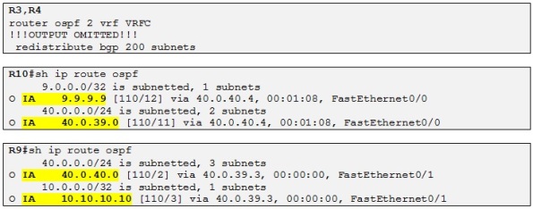
So now let´s redistribute MP-BGP into OSPF on R3 and R4 and check if R9 and R10 are receiving the different prefixes:
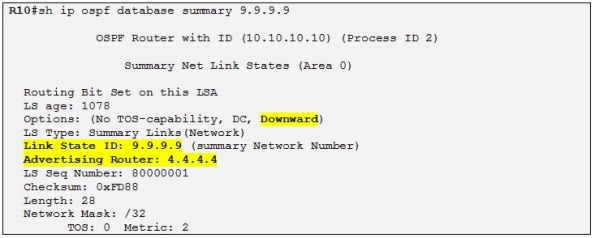
Alright so Both CE routers are receiving the prefix from each Customer C site. Also the OSPF routes are LSA Type-3 because as I explained before the MPLS VPN is considered a OSPF super backbone area and all the PEs are acting as ABRs. Let´s have a closer look at the LSA Type-3 for 9.9.9.9 on R10:
We can see that the down bit has been set by the PE router, in this case R4. As I explained before the down bit is a loop prevention mechanism for dual homed OSPF domain and a PE receiving an OSPF LSA with the down bit set will not redistribute it into MP-BGP effectively avoiding potential routing loops.
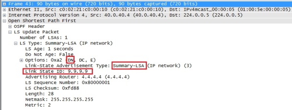
If you look at a Wireshark capture for the same LSA we can see the same information:
We can see that the down bit is set in the LSA header option field
In our case as the backdoor link is not functional yet it doesn´t matter really if the down bit is set or not. Moreover if we enable the backdoor link between R9 and R10 when the Customer site C where R11 is located is not active R3 and R4 will prefer intra-area route and no loop will form as they will not redistribute MP-BGP route into OSPF as the AD of OSPF will be preferred to the AD of iBGP 200. Let´s try to enable the backdoor link and see how the OSPF database looks like on R3:
As soon as we enable the backdoor link between R9 and R10, R3 and R4 learn the loopback of both R9 and R10 and intern links as intra-area route instead of LSA Type-3 previously:
This means that even if they still advertise these routes to each other via MP-BGP:
They will not be able to redistribute them into OSPF as the AD of OSPF 110 is taking precedence over the AD of iBGP which is 200. That also means that the OSPF database for VRFC will not contain any LSA Type-3 summary anymore.
Side note: After enabling the backdoor link, R3 and R4 will tell the other OSPF routers to remove the previous LSAs Type-3 by advertising these LSAs with an infinite metric (16777215) into the OSPF domain.
So in this case the routing loop is prevented by the help of the AD. But let´s consider now that the customer C site where R11 is located comes now online. Then we can predict that the down bit will be useful in this case as the loopback originated from R11 (11.11.11.11/32) will be advertise in OSPF domain of R9,R10 as LSA Type-3 and potentially loop when propagating from R4 to R10, then to R9 and then to R3. Then R3 will advertise it back to R4 again and so on. Thanks to the down bit, in this scenario R3 will not redistribute the loopback of R11 into MP-BGP again. Let´s power on R11 (everything is already configured as illustrated on the topology diagram.
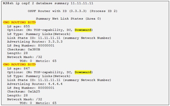
As soon as R1 advertise the loopback of R11 through MP-BGP both R3 and R4 receive it, and redistribute it into OSPF as a LSA Type-3 with the down bit set:
The down bit is set and the routing bit is cleared so this prefix will not be installed in the routing table of neither R3 nor R4 which prevent R9, R10 OSPF domain to be considered as a transit path for routing this prefix. So R3 and R4 always use the MPLS VPN backbone when making routing decision for traffic destined to R11 site:
Side note: The routing bit is cleared as I explained before because a PE receiving a LSA Type-3 with the down bit set will automatically clear the routing bit for this prefix. Please also note that the down bit is only set on LSA Type-3
That means that this prefix should be present in the routing table of R3 and R4 for VRFC as a BGP internal route and not as an OSPF inter-area route although the AD of OSPF is better than the AD of iBGP 200:
If we were to originate an external route (111.111.111.111 /32) into OSPF on R11 we would see the following on R3:
Side note: recall that to redistribute from OSFP into BGP you have to use the keyword match external as by default BGP will not redistribute OSPF external routes.
If we analyze the BGP extended communities for this prefix we conclude the following:
- Route Type: 0.0.0.0:5:1. Indicates area 0, LSA Type 5 and metric type E2
- OSPF domain ID: 0x000000020200. Indicates an originate (on R1) OSPF process ID of 2
- OSPF Router ID: 40.0.11:1. Indicates the OSPF RID of R1
Now if we were to change the OSPF domain ID to 3.3.3.3 on R3 let´s see what happens looking at the OSPF database of R3:
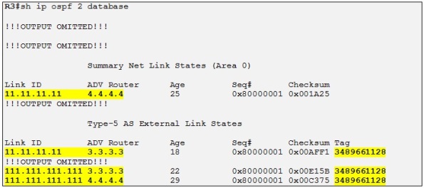
R3 is learning R11 loopback prefix as before but the domain ID is now different from the one configured on R1, R3 redistribute the Prefixes learned from R1 coming from R11 as LSA Type-5 into the OSPF domain of R9 and R10. We can see that 11.11.11.11 /32 is now advertised as LSA Type-5 by R3 but still as LSA Type-3 by R4 as R4 still has the same OSPF domain ID as R1. 111.111.111.111 /32 is advertised as LSA Type-5 by R3 and R4 in any case as it is an original LSA Type-5.
Notice the tag which has been set by R3 and R4 when redistributing the MP-BGP route into OSPF. This tag is equal to the AS number of R3 in this case and it is used to prevent routing loop when using LSA Type 5 as the down bit is not supported on this type of LSA. So when a PE receives a LSA Type 5 with a tag equal to its own BGP AS number it doesn´t redistribute the prefix into MP-BGP effectively preventing eventual routing loops. Actually the LSA Type-5 with the tag equal to the AS number has the routing bit cleared also so the receiving PE never installs it its VRF routing table from the OSPF database. As the prefix is not present in the routing table as an OSPF route it will never be redistributed into MP-BGP.
Site note: A routing loop could actually be created for the prefix 111.111.111.111/32 if we were to remove the tag automatically set by the PE router which by default is equal the AS number. We could for example remove it by setting another tag (for example 444) when redistributing this MP-BGP route into OSPF. Then when the other PE receive the prefix via OSPF the tag will not be equal the AS number and therefore the loop prevention rule will be defeated. The routing bit will be set and the route will appear in the VRF routing table as OSPF E2. If the PE were set to redistribute also OSPF external (disabled by default in BGP), then the PE (for example, could be R3 in our example) will redistribute 111.111.111.111/32 into MP-BGP and then it will be up to R4 do decide with originating PE it prefers to route traffic for this prefix (R3 or R1 which is the originating). If R4 would prefer R3 than a routing loop will be created and the traffic destined for 111.111.111.111 from R4 will loop through R3, than R9, R10, back to R4, R3, etc. We could check this behavior by debugging on MPLS packet on R2 and R3. Then when the TTL is exhausted the loop will stop. Interesting 🙂
The last topic I would like to talk about is OSPF sham-Link. Let´s reset the domain ID on R3 as it was at the beginning before continuing on with OSPF sham link.
OSPF Sham Link
Let´s consider that the backdoor link between R9 and R10 is a Low-Bandwidth link and it should only be used for backup purpose in case that R9 and R10 sites lose connection to the ISP MPLS VPN backbone. The issue though is that as we have seen before R9 and R10 sites are in the same OSPF area (area 0) and therefore learns each other prefixes as OSPF intra-are routes. Both PE routers, R3 and R4 will advertise these prefixes into each CE site as LSA Type-3 or LSA Type-5 as we saw before if the OSPF domain-ID was different on R3 and R4. As per OSPF route selection critera, intra-area routes will always be preferred over inter-area routes which in turns mean that the backdoor link will always be preferred over the MPLS VPN backbone.
In order to resolve this specific case and reestablish the desired path selection over the MPLS VPN backbone an additional OSPF intra-area (logical) link between ingress and egress VRFs in the relevant PE must be created. This link is called a Sham Link.
Side note: A Sham Link is required between any two VPN sites that belong to the same OSPF area and share an OSPF backdoor link. If no backdoor link exists between the sites, no sham link is required.
To configure a sham link a /32 address space is required in each PE router for each sham link.
The /32 address space:
- Is necessary so OSPF packets can be sent over the MPLS VPN backbone to the remote end of the sham link
- Must belong to the CE VRF
- Must not be advertised by OSPF
- Must be advertised by BGP
Alright so let´s configure two loopbacks on R3 and R4 with IP 33.33.33.33 /32 and 44.44.44.44 /32 respectively and advertise them into MP-BGP:
Side note: These loopbacks must not be present in the OSPF VRF process 2 because otherwise the sham link will fail as both PE will route for these addresses over the CE OSPF domain and not the MP-BGP backbone.
Side note 2: In our case both PEs will advertise the loopback of each other into OSPF but that is not an issue because a connected route will always be preferred over a routing protocol advertised route. Moreover the routing bit will be cleared as these prefix are redistributed from MP-BGP into OSPF as the result of the LSA Type-5 automatic tagging OSPF prevention rule for MP-BGP MPLS environment.
Last step in configuring sham link is to create the proper sham link between the two PE routers (R3 and R4) under the PE-CE OSPF process:
As soon as we enabled the sham link on R4 we can see the following output in Wireshark:
Basically R4 sends OSPF unicast hello packet to 33.33.33.33 (R3) in order to establish the sham link. As R3 is not yet configured no response is received back. Note that the OSPF unicast hello is tunneled through the MPLS backbone by using two labels, the transport label which is 17 which correspond to IP BGP peering session of R3 (which is the next-hop) and the VPN label which is 24 which indicate to R3 in which VRF the routing lookup should be done when receiving the packet. Let´s enable the sham link also on R3 and check how the sham link adjacency is done:
As soon as we enable the sham link on R3 an OSPF adjacency is formed between R3 and R4 through the MPLS VPN backbone:
Then the normal OSPF database exchange process is occurring (see my previous post on OSPF to know more details about the OSPF database exchange process) and we can confirm this with the following Wireshark capture:
So in this case R3 is sending a LSDB summary to R4 for the LSA it knows about and R4 will do the same. When both LSDB are synchronized, R3 and R4 will form full adjacency over the sham link.
Let´s check the status of the sham link on R3:
Side note: The sham link is considered a demand circuit (DC) by the OSPF process in order to reduce the traffic flow over the sham link. This implies that the regular LSA will flood over the sham link but the periodic refresh traffic is avoided.
Alright! As our final step in this topic, let´s check how traffic is routed from a perspective of R9 for the prefix 10.10.10.10 /32 which is R4 loopback IP.
So even if we have created the sham link over the MPLS backbone R9 still prefer to route via the backdoor link to reach R10´s loopback with a metric of 2. Let´s have a look at the OSPF database to find out how the OSPF process of R9 did calculate that the best path to 10.10.10.10 was via R10 and not R3 (PE).
First R9 does a LSA Type-1 lookup on himself to see who he is connected to:
So R9 is directly connected to the DR with a metric of 1. So now R9 must perform a LSA Type 2 lookup on the DR:
So R10 is also connected to the DR, so now R9 do a LSA Type 1 on R10:
So R9 sees that the 10.10.10.10/32 prefix is directly connected to R10 and has a metric of 1. So total metric is: 1+1=2 (metric to reach the DR and metric to reach the loopback of R10).
If R9 were to choose the path via R3 instead to reach 10.10.10.10 /32 the metric will be:
So 1
+ 1 (cost over the sham link)
+1 and then +1 for the loopback as we saw before resulting in a total metric of 4. That is why R9 prefer to route over the backup link to reach prefixes in R10 site. So let´s just increment the cost of the backdoor link to 10 on both R9 and R10 and let´s check the result:
Perfect! So the desired result is achieved and both R9 and R10 are now routing over the MPLS VPN backbone to reach each other prefixes. The backup link will only be used if the OSPF sham link is down.
Thanks for reading!
/Laurent



















Great post
Thanks 🙂
Laurent,
Thank for this detailled step by step howto. Can you please post a working link for the GNS3 files. I will build them myself as well but I will use yours as a verification when having problems
Thank you in advance.
No problem. I have attached the GNS3 files a the end of the post 😉
/Laurent
well done 🙂 thanks
Awesome!!! I never seen such clear explanation of PE-CE Ospf interworking. Thx a lot!
You are welcome. I am happy that you found it useful.
/Laurent
Thanks for sharing! Your writing is very helpful. Keep good works!
Thanks a lot.
/Laurent
really really great post!! thank you for sharing
Thanks a lot.
/Laurent
that great very useful link……can i get the same for all the MPLS INTER VPN’s Options like OPTION A OPTION B and OPTION…
Thanks
Perfect…………………….
Thanks so much for writing all this up! I found it very helpful and informative!
Good! The way you explained MPLS VPN is Really awesome
I wish I have seen this site long back.. Great work thanks for helping people around you !! Can you also give us the debug commands you are using to verify route updates
thanks for your post
i want to run this project but,i cann’t run it and i faced with this error:
cann’t connect to the hypervisor 127.0.0.1:7200 : [errno 10061]…
i want to fix this error but the solutions( like below post ) aren’t work.
http://forum.gns3.net/topic1247.html
what should i do?
thanks for your post
First ,, the words can’t explain what I could see for this clear explanation
but I think that the link for the configuration file is deleted
Could you please upload it again ?
Many thanks for this Post, very informative
This is the best post on MPLS. Can you reattach the GNS Config Files.